SMD Soldering Practice Journey - Part 03 (The Huge Discovery)
I am actually struggling in this stage. I tried to tracr the PCB exactly as intended and then it just won't turn on.
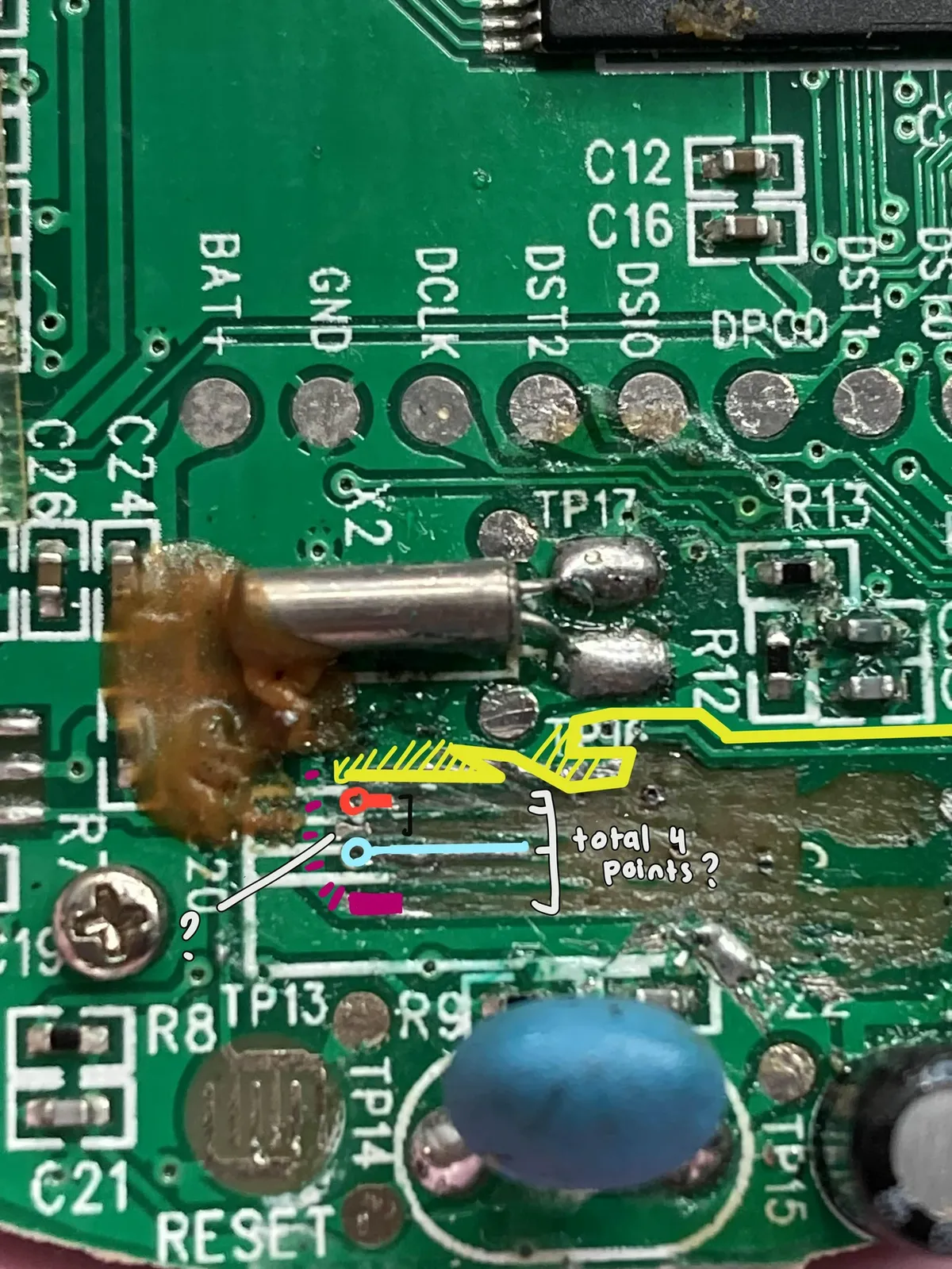
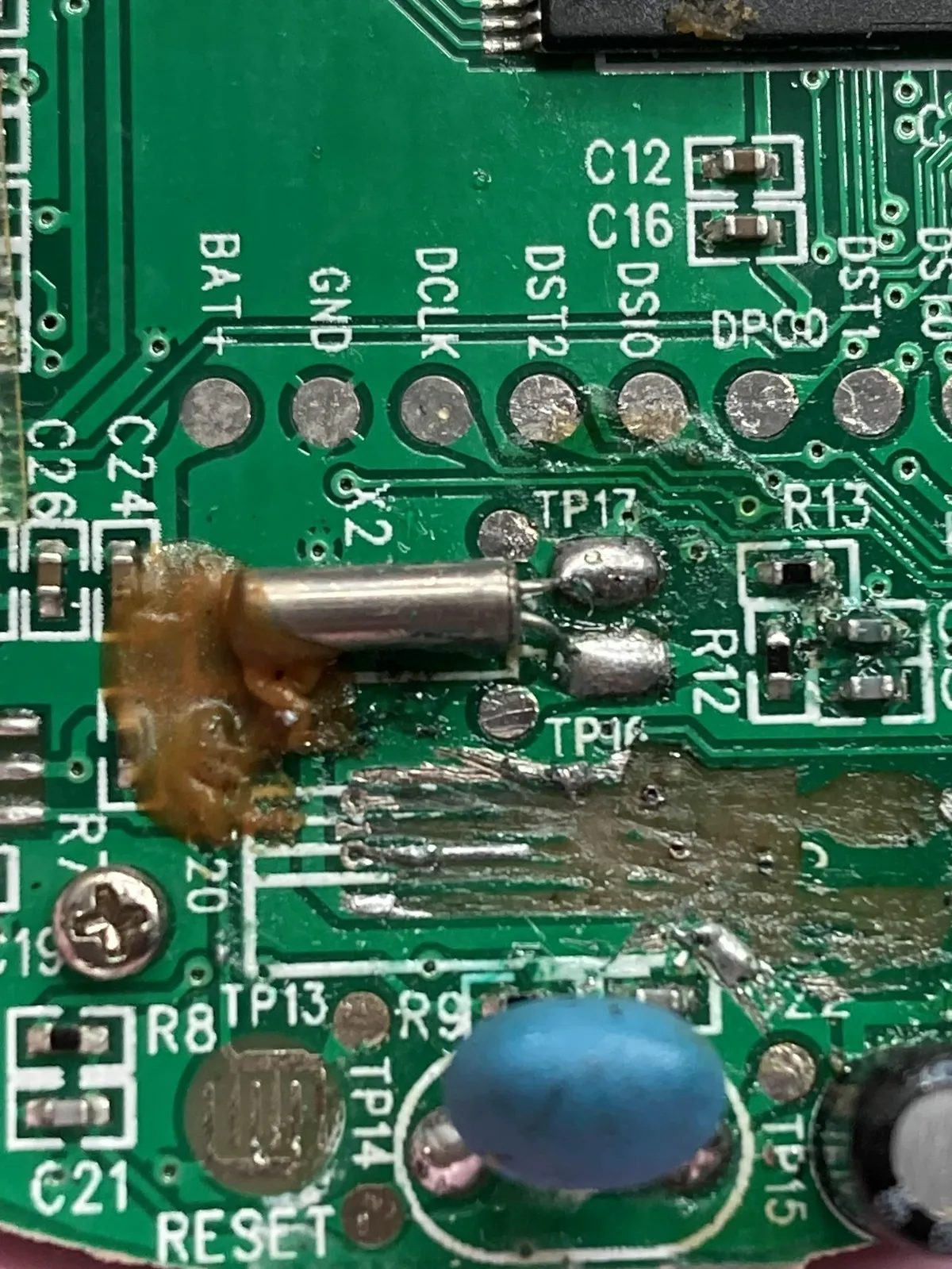
So I tried to look at what is happening, drawing over the photo of the board
I might have connected it to the wrong one. I also did a voltage test and the electricity definitely did not go through every single components. So I'm wondering if I have cut access to the other components or not.
But that being said, I eventually watched this playlist video from Learn Electronics Repair on Youtube in which I decided to go back to the fundamentals. I feel like I have always been avoiding the fundamentals/basics of electronics because of the math aspect, but this playlist actually helps me to understand the practical side of it!
I also did watch this video from Learn Electronics Repair about fixing faulty components without schematics, basically my intention to adopt the blueprint of how the person is determining the faulty component without any clear direction, than actually following it 1-on-1.
Here's what I found: The person tried to understand what is going on without math from the power supply and where it goes. I like how the approach is very practical and less textbook style. Every chips schematic is being searched and basically take into summary what it's doing than trying to immediately 100% understand it.
So let's try to apply it to this Tamagotchi iDL PCB! [insert zoomed in image of IC chip here] I see that this type of IC chip and searched online for the documentation, and here is the online pdf I found. For now I put it in my backlog online.
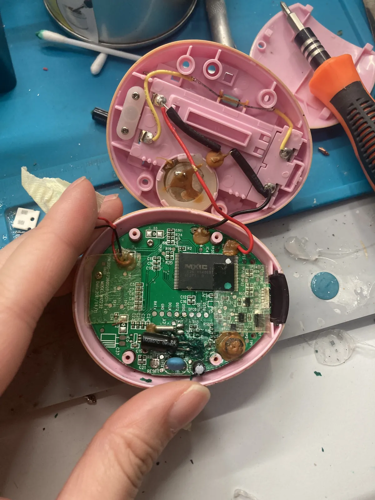
I was getting quite frustrated that the cable that is linked to the speaker now is loose and started to just took off
I think this is the point where I'd share that if just using soldering iron instead of copper wire would turn on but it does not, although I tested for continuity test and it does buzz my multimeter. Guess what, it didn't turn on either.
Here is my raw reaction: I was frustrated reached out for my friend who did dabble a bit with some electronics knowledge and actually designed his own PCB. He kind of suggested if I could purchase a thermal camera so that I could see the possible traces and or short circuits, but getting thermal camera is really out of my budget. It's also important factor that he said this because it reminds him of how he watched other people doing it on the internet. So I decided to just see what's on Youtube, looking at raw electronics repair.
And so I did find this video on Youtube Channel that I'm more interested in seeing the person's thought process than seeing the result.
Very important to highlight that he used phone flashlight to identify the PCB traces than using thermal camera, and testing if there is any shorts using continuity test on the multimeter. I'll say, this changes everything
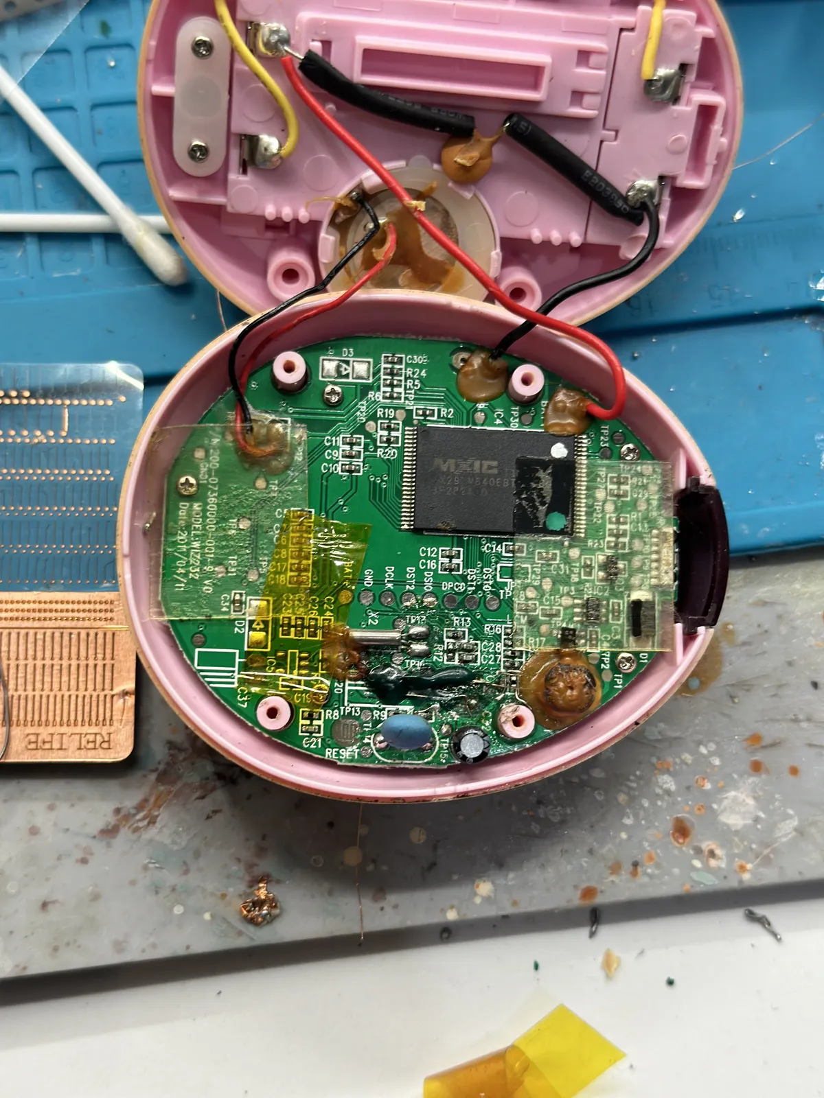
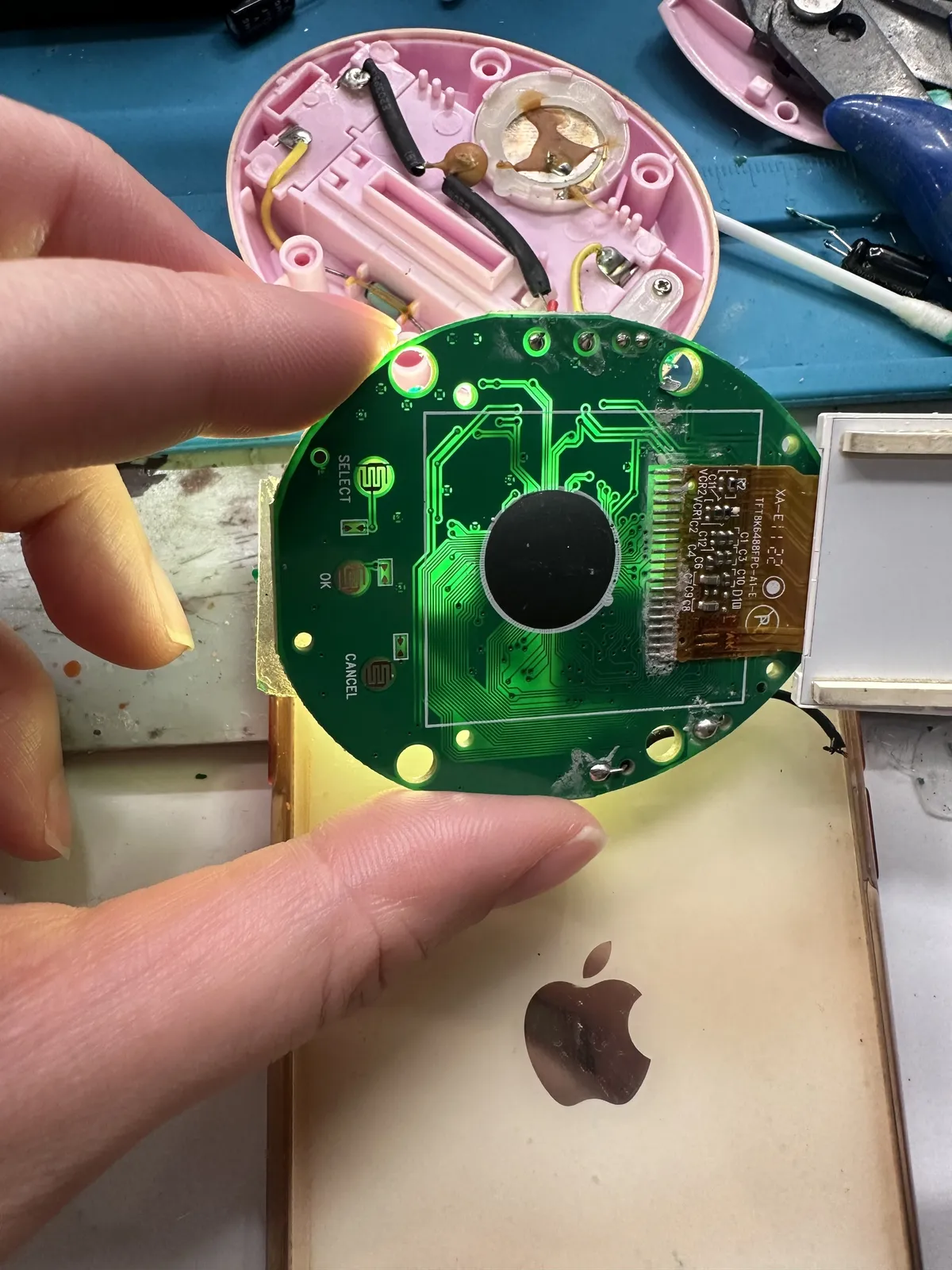
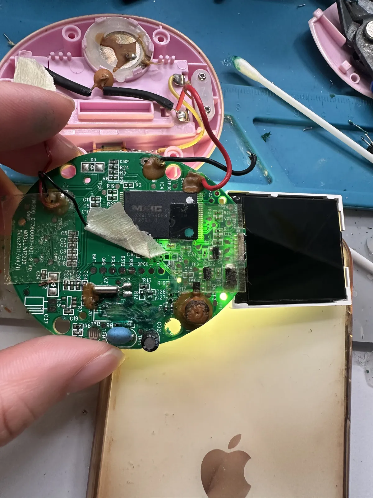
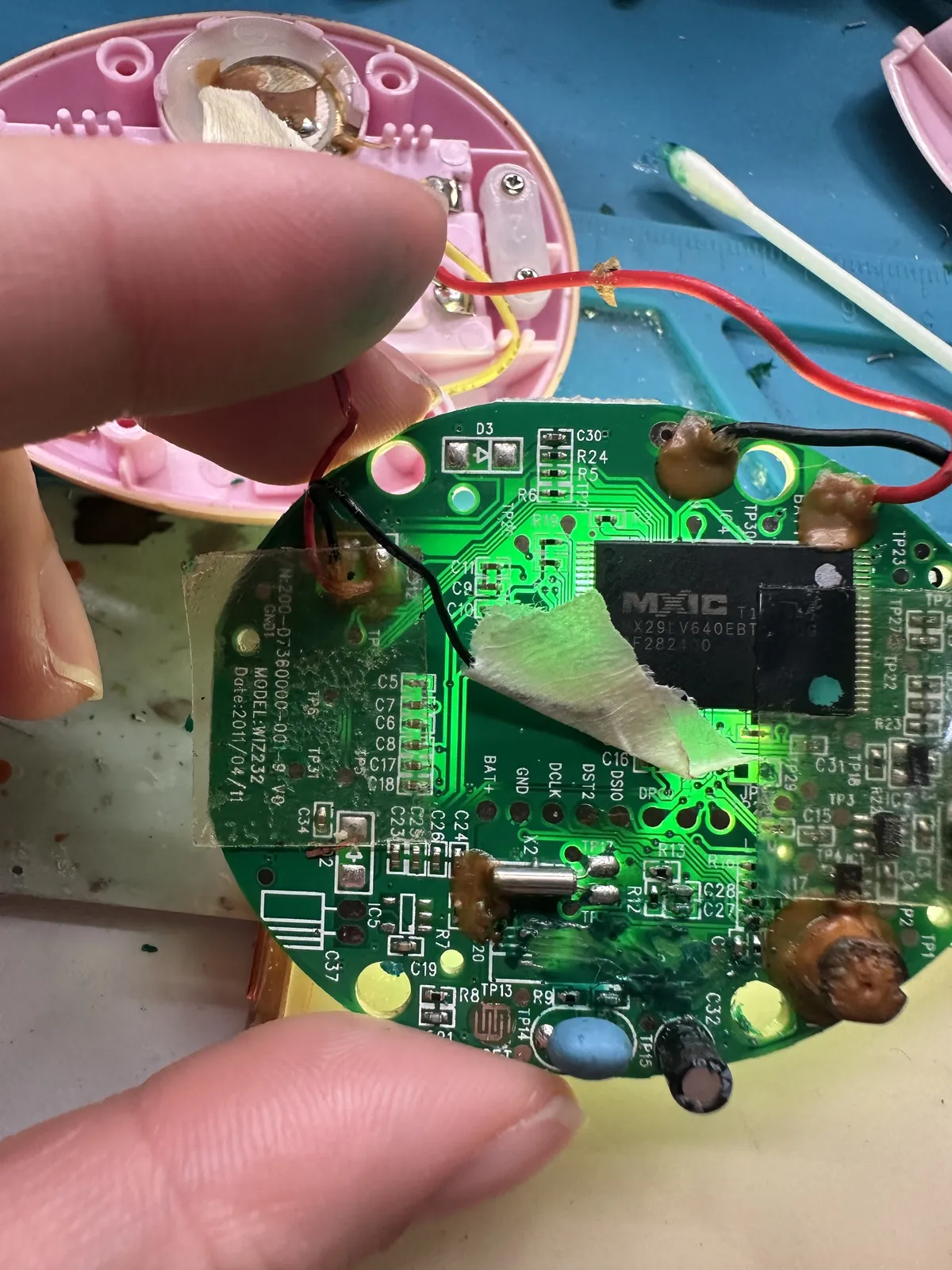
But seriously, when I took off the screws and just take a very overall look of the PCB, turns out it has two normal-sided PCB with a screen
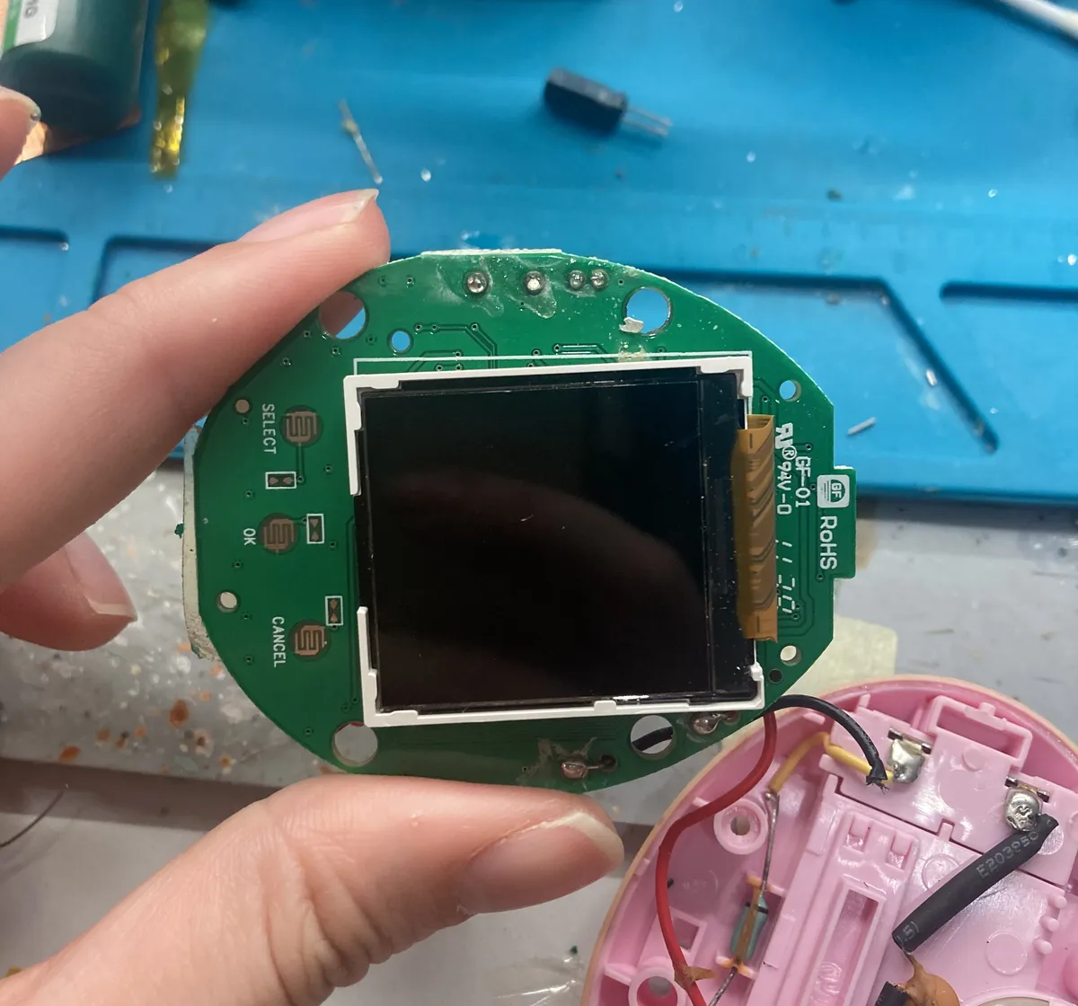
Here are more pictures I took of the PCB.
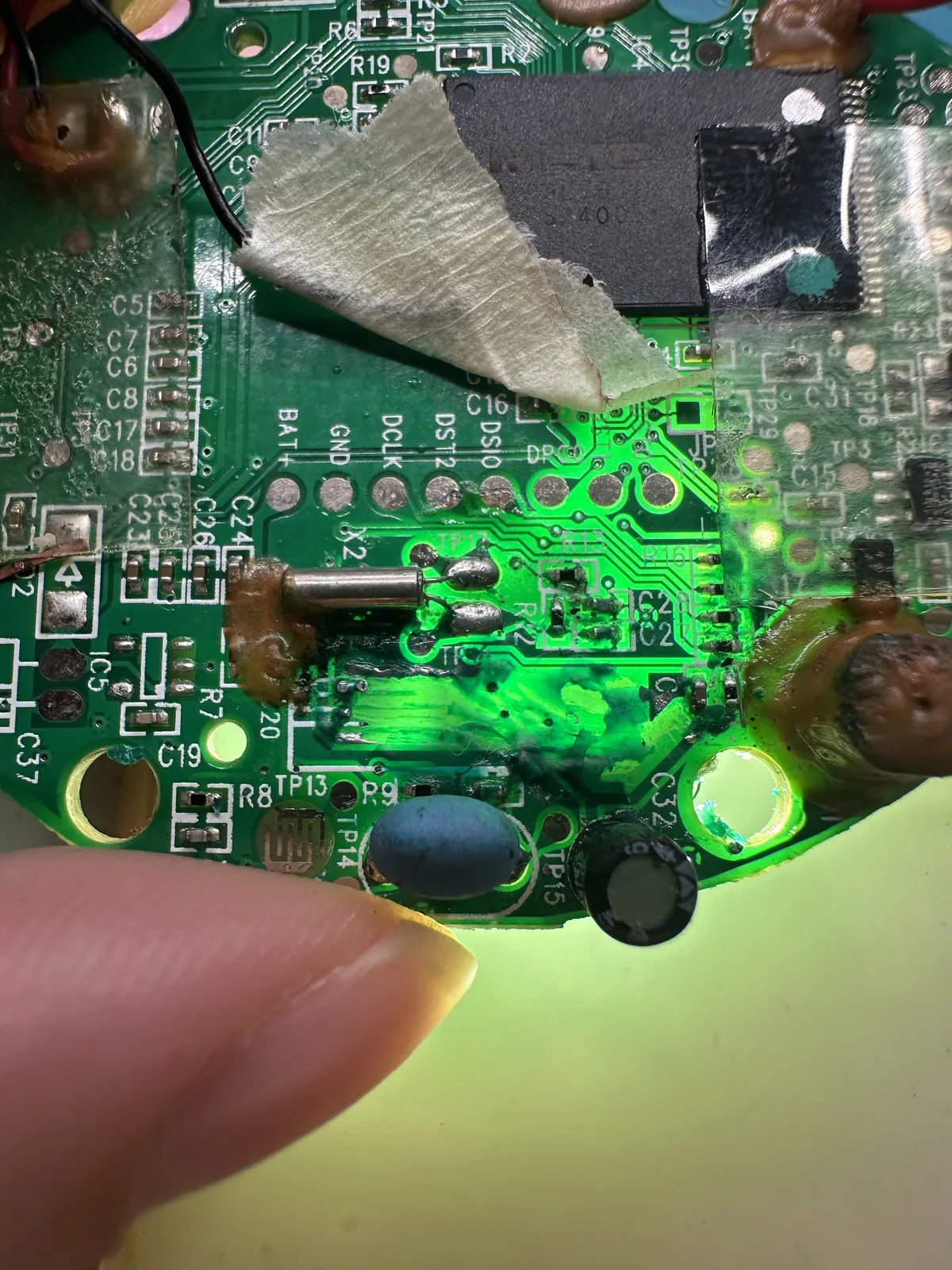
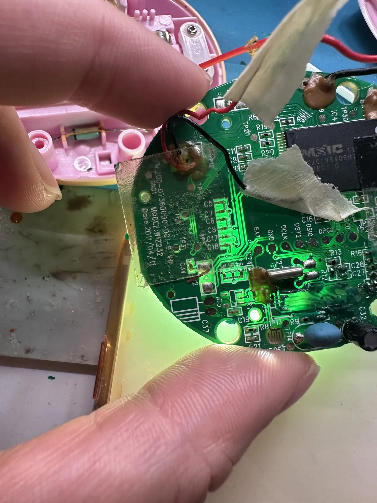
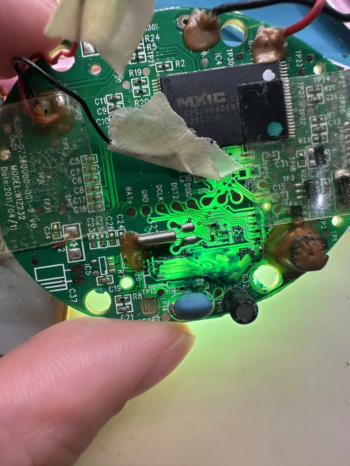
Here's what I found: When I burned the capacitor solder pads, I might have burned the connection from the other side as well because it's connected. As shown in the dots below and the other side
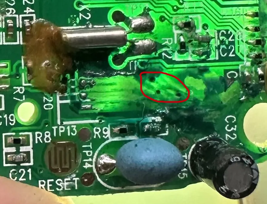
So my hypothesis is that, my copper wire should also touch the points. Also it's important to note that my copper wire is enamel coated, so I'd have to slightly melt the enamel so that I can have the soldering iron sticking to it. My hypothesis is based on this Youtube Video on how this person repaired PCB trace with copper wire, plus using the UV solder mask
My whole life learning and having science and engineering project taught me that theory doesn't always 100% convert to actual solution but it probably gives a direction. Whether it's true or not, we have to test it.
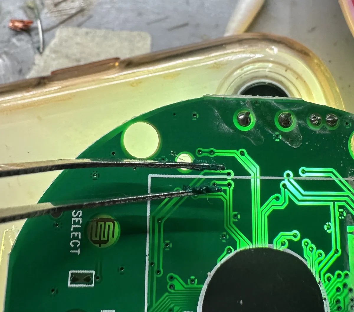
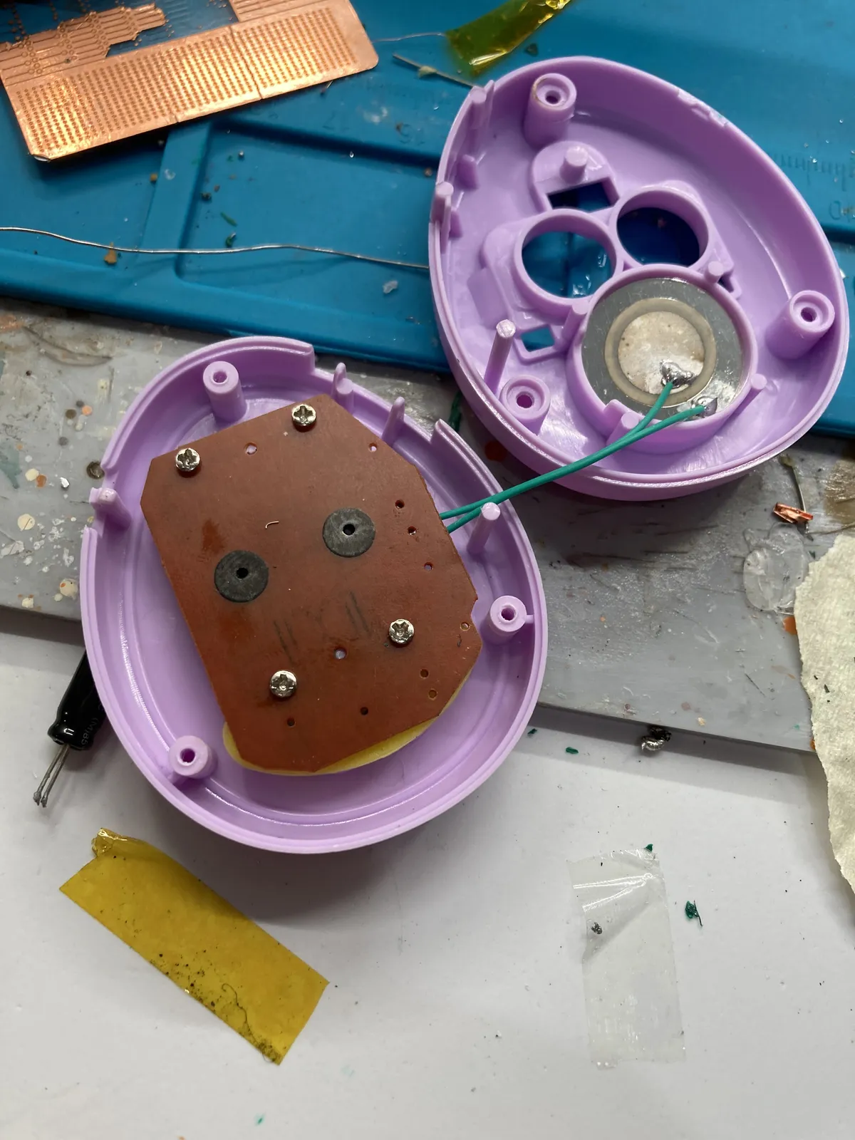
That being said, I did have this experimental "168 in 1 BunnyRom" virtual pet that I bought very cheap online, took it off and it does have massive difference in the PCB especially how it's only one sided. Picture below show a conductive circular pads for the battery terminal.
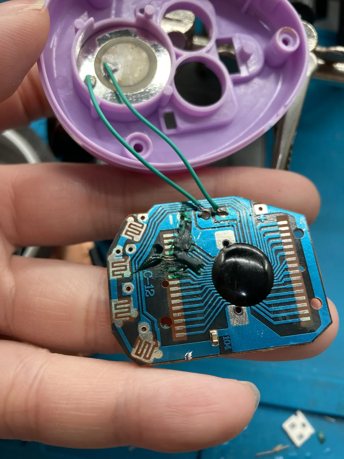
I did manage to solder down the pads but it won't turn on. As shown below.
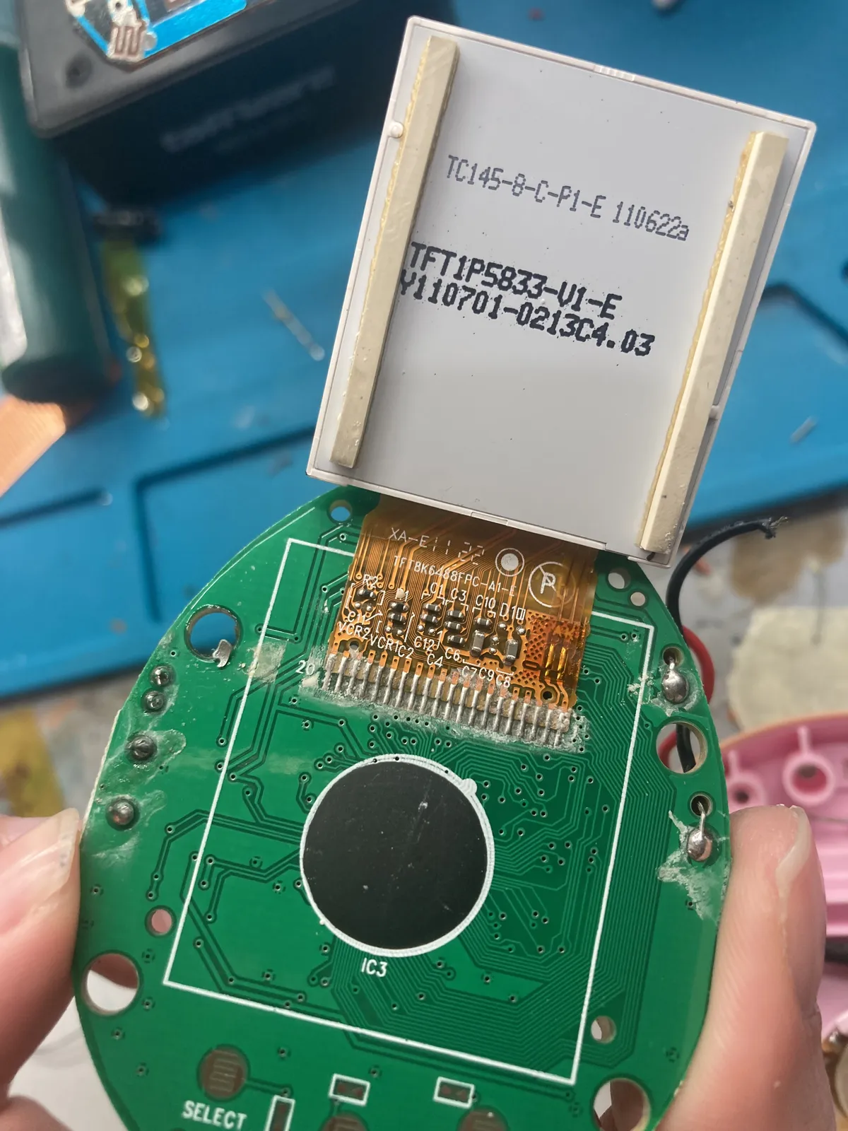
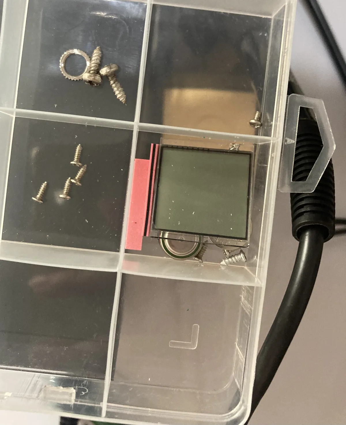
After I researched the type of the LCD, turns out it is actually a zebra stripes. I found that in this forum that it works by relying on the pressure tight enough, but it's really a problem for this technology
So I tried to get the conductive pads just be clean enough, still won't turn on.
Another issue is that I did accidentally took off the zebra stripes so, let's see if we can do anything to modify the components for this virtual pet without destroying the "blob" or black epoxy. I mean this is for a teardown experiment so I'm glad I just did try something with it.
On the next blogpost, I will try to review the basics of the electronics and try to trace the schematics of the photo of the Tamagotchi iDL 15th Anniversary, figuring out what's happening and where things go. Then I'll test my hypothesis to connect the copper traces to the dots as I explained above but not yet turning on the power supply or battery.
Hope you enjoy this more of a chatty blog post, I'll see you on the next update!